Introduction:
In this project we were allowed to build a smart groundwater system for the company Hooybergs NV. Here we used ESP32, angular and DotNet. We built our system so that the user can completely control how much is pumped and at what termein. Also, the pumps will shut themselves down when something is broken. The system is also made so that it can correct itself.
Teammember:
- Wouter Vandueren
- Jan Vanhove
- Lander Wuyts
- Taro Verschueren
- Hilde Hemelaers
Used technologies:
- angular
- .net
- tailwind
- esp32
- python
my role in this project:
I was mostly concerned with writing the arduino code. Therefore, more explanation of this is given below. Also, I still created the frontend of our webapp. This way Hilde could deal with the backend and I could deal with the frontend.
Project4.0 - IoT
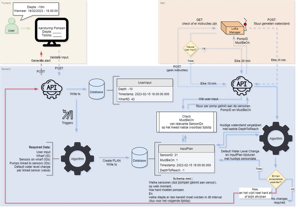
Scheme
Manager
The manager is the brain of the IoT system for this assignment. It stands in between the database (on the internet) and the sensor/pump-modules.
Overview
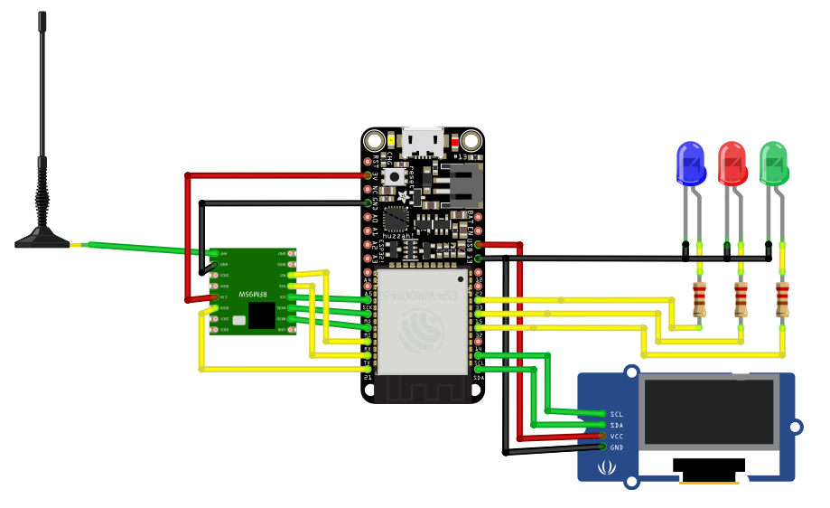
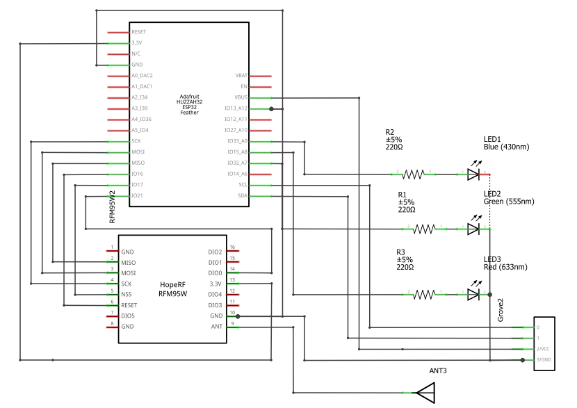
components:
- ESP32 feather
- LoRa RFM95 SX1246 868Mhz
- OLED lcd GME 12864-41
- Antenna
- LEDs
- Buttons
- Resistor 220 ohm
How does it work?
The manager is continuously listening to the database. When There is a change, it will process the data en send it to the right destination. Every X minutes, the manager receives data from the sensors, batteries, flowrate,... . The manager is sending this data to the database, so the user can view this data on the webapplication and our algoritm can use this data to make this system smart.
Connection with the agents
First: the connection with the agent and how the manager knows what data is sent/received by whom. The data is sent/received over a LoRa connection.
LoRa is a physical proprietary radio communication technique. It is based on spread spectrum modulation techniques derived from chirp spread spectrum technology. It was developed by Cycleo, a company of Grenoble, France, later acquired by Semtech. LoRaWAN defines the communication protocol and system architecture
Every module has it own channel to send data to. Thanks to this channels, the modules know what messages they need to listen to and what messages they can ignore.
When data is sent by the LoRa connection, it is done so in a string format with separators in between.
Connection to the database
The database is hosted on azure. For a connection to the database, the Manager module is connected to the internet. Every X minutes, the manager is sending a Get-request for receiving all the necessary data from the database. When the manager needs to send data to to the database, it is sending a specific post request.
Security
Of course, security is pretty important for any IoT system, so there are some security protections
implemented here as well.
First, through a secure connection between the database and the database over
HTTPS, which means the data is encrypted.
Second, the connection between the manager & agent is
also assymetrically encrypted. It uses a mathematically related pair of keys for encryption and
decryption: a public key and a private key.
Mockup
On the mockup of the manager, there are 3 LEDs installed. Every LED has its own functionality:
| Color | Function |
|---|---|
| Red | error |
| Yellow | communication with LoRa data |
| Blue | Communication with database |
| all blinking | trying to connect to wifi |
Pump agent
This code is an example of an Arduino Sketch that receives LoRa messages and performs various actions based on the message received. The code makes use of several libraries, including 'Arduino.h', 'SPI.h', 'LoRa.h', 'Cipher.h', and 'Servo.h'.
The code sets up several pin modes for relays, initializes the serial monitor, and sets up the LoRa transceiver module. It also initializes a cipher object and the SPIFFS file system.
The 'sendMessage' function sends a message through LoRa with specified destination address, sender address, message ID, and payload.
In the 'setup' function, the pin modes for the relays are set, the serial monitor is initialized, the LoRa transceiver is initialized, the cipher is set with an encryption key, and the SPIFFS file system is started. A servo motor is attached to pin 16.
In the 'loop' function, the code listens for incoming LoRa messages and processes them. If a packet is received, its header is read, and if the recipient address matches that of the device, the payload is decrypted and processed based on the contents. The code also tracks the state of several relays and servo motor positions.
Overview
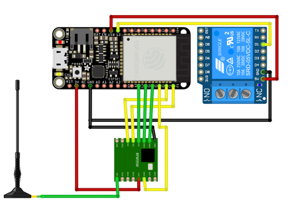
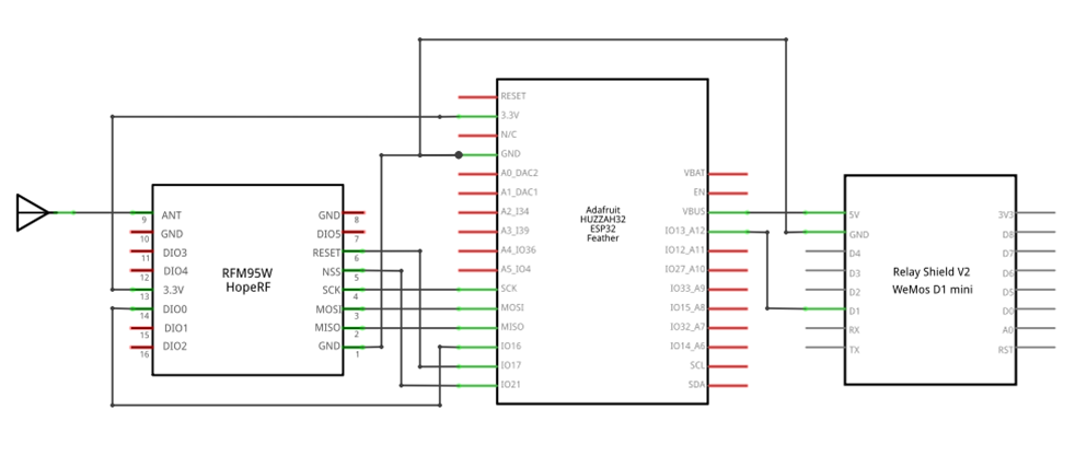
components:
- ESP32 Feather
- LoRa RFM95 SX1246 868Mhz
- Antenna
- Relay
How does it work?
The ESP32 is the brain of this system. It receives the data from the manager module through the LoRa component. It receives the following string:
true|false
The first value is for the pump status. The second value is for the sensor status. The values are being used for setting the pump/sensor relay on or off. For security reasons, this data is encrypted in transit, so that no one should be able to remote control the pumps. When de status of the sensor or pump is changed, the module sends a "succesful" message back to the manager module. It does this, so the user can view if his/her changes worked or if something went wrong.
Sensor agent
This is the module that is sending all of the sensor data. The data is sent tot the Manager Module. The module does not receive any data, it only sends data.
Overview
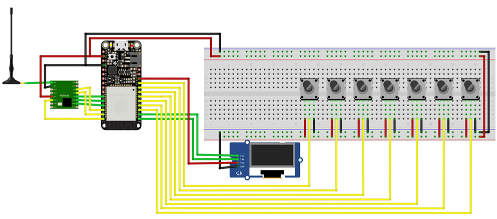
components:
- ESP32 Feather
- LoRa RFM95 SX1246 868Mhz
- Antenna
- Potentiometers
- OLED lcd GME 12864-41
How does it work?
There are 7 potentiometers on the module, which are used to simulate all the necessary date needed to make this system smart.
data:
- value sensor 1
- value sensor 2
- energy consumption sensor 1
- energy consumption sensor 2
- energy consumption pump 1
- energy consumption pump 2
- flowrate
All the data is placed one after the other, with in between a seperator. Than the string is encrypted and forwarded to the manager module. The raw string is as followed:
150|46|86|120|0.5|8.4|4.9
The LCD is for reading all the data on the module itself.
Additional commentary on the function of the code
This is an Arduino code that reads data from different sensors and displays the data on an OLED display. The code is also capable of transmitting the data via LoRa (Long Range Radio) to another device, which can receive and process the data.
The first part of the code includes all the necessary libraries to run the code, including the standard libraries for Arduino, SPI, Wire, and Adafruit_GFX and Adafruit_SSD1306 for the OLED display. The LoRa library is also included for the LoRa communication and the Cipher library is used for encryption and decryption of data. The code also includes a library for file management called SPIFFSTest.
In the next part of the code, all the pins are defined that are used to read data from the sensors. After that, all the ID's are defined which are used to identify the data coming from the different sensors.
Next, the code defines the minimum and maximum values of the sensors and their corresponding minimum and maximum values in the form of constants. This is used later in the code to convert the analog data received from the sensors to a value that can be understood by the system.
The OLED display has a width of 128 pixels and a height of 64 pixels, which are defined as constants.
The LoRa module uses the pins ss, rst, and dio0 which are also defined as constants.
The code also defines two global variables, man and sens_agent, which are used as addresses for the LoRa communication. The msgCount variable is used to keep track of the number of messages sent.
The variables sensor1Value, sensor2Value, flowRate, energyPump1Value, energyPump2Value, batterySensor1, and batterySensor2 are used to store the data received from the sensors.
The PacketEncrypted and PacketDecrypted variables are used to store the encrypted and decrypted packets of data.
The function converter and converterInt are used to convert the analog values received from the sensors to their respective values in the form of minimum and maximum values.
The sendMessage function is used to send messages via LoRa. It takes two arguments, the outgoing message, and the addresses of the sender and receiver.
The setup function initializes the serial communication and sets the encryption key for the Cipher library. It then starts the file system, lists the files in the directory and initializes the OLED display.
The main loop function continuously reads data from the sensors, converts it to the desired format, displays it on the OLED display, and sends it via LoRa if the conditions are met.